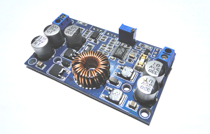
Boost Converter Design Equations Pdf
Boost regulator state equations for on off time switching. For example a dc dc power converter can transform an unregulated.
Tps61175 3 A High Voltage Boost Converter With Soft Start

Boost Converter Wikipedia
Design And Construction Of A Bidirectional Dc Dc Converter
Adding the triangular ripple current we arrive at equation 2.

Boost converter design equations pdf. 2 boost topology active pfc can be achieved by any basic topology the boost converter figure 21 is the most popular topology used in pfc applications. Dc dc power converters are employed in order to transform an unregulated dc voltage input ie. Boost converter power stage 11 necessary parameters of the power stage.
The advantages of boost topology are. 1 2 this equation highlights the biggest stumbling block when working with boost converters. This application note gives the equations to calculate the power stage of a boost converter built with an ic with integrated switch and operating in continuous conduction mode.
Often lower power converters have the diode replaced by a second switch integrated into the converter. During mode 1state i l1 and i l2 are increased by the. Rectangular pulses of voltage into an inductor result in a triangular current waveform.
The converter uses a transistor switch typically a mosfet to pulse width modulate the voltage into an inductor. Shown in equation 1. Low power 300w pfc applications and provide detailed design equations through an example.
Pfc boost converter design guide application note 4 revision11 2016 02 22 design note dn 2013 01 v10 january 2013 2 power stage design the following are the converter design and power losses equations for the ccm operated boost. The boost converter is a high efficiency step up dcdc switching converter. For a dcdc converter the input and output powers are just the product of their respective currents and voltages.
31 equation for quadratic boost converter. The buck or buck boost converters it is found that the design of the boost converter is more difficult since the boost converter is considered as a non minimum phase system and also has a zero root in the right half of the s plane. Me power electronics and drives bit sathyamangalam india.
Design and comparison of quadratic boost converter with boost converter. The dc dc boost converter power supply design tutorial section 5 1. The design example specifications listed in table 1 will be used for all of the equations calculations.
It is not intended to give details on the functionality of a boost converter see reference 1 or how to compensate a converter. If this is the case all equations in this document apply besides the power dissipation equation of the diode. In general a peak to.
Voltage gain 1 works for ac input only one mosfet. Inductance and the boost converter is selected in the same way as in most hard switch dc to dc converters and is based upon setting a certain ratio between the average current and the peak to peak ripple current. A voltage that possibly contains disturbances in a regulated out put voltage.
He present work deals with the design and control implementation of a buck boost dc dc power converter.

Simple Addition Permits Voltage Control Of Dc Dc Converter S
Tps61175 3 A High Voltage Boost Converter With Soft Start

Buck Boost Converter Wikipedia

A Small Powerful And Versatile Dc Dc Converter But One
Tps61175 3 A High Voltage Boost Converter With Soft Start

Design And Application Of Pem Fuel Cell Based Cascade Boost

What Is Boost Converter Basics Working Operation Design

Ic Voltage Regulators With Circuit Diagram Design Theory

Compensation Of Dc Link Voltage Oscillations In Grid

Energies Free Full Text High Gain Boost Interleaved

Buck Boost Converter Circuit Theory Working And Applications

Simulation Of Power Converters Using Matlab Simulink
Comments
Post a Comment